Blogs
Exterior Surface (Mold Cavity) Design
First we talked about Interior Surface (Mold Core) Design, link to the blog : http://cmppin.com/blog/interior-surface-mold-core-design/
The inner and outer walls of the part are formed simultaneously and integrally, but interior and exterior designs are essentially independent so we review them separately. As the design develops, the designer should begin thinking about the interaction of the plastic and the mould that will produce the part. The visual exterior of many products is formed in one half of the mould called a cavity. Following are some of the features of mould cavities the designer will want to consider.
Cavity – Cavity Blow Ratio = W>D
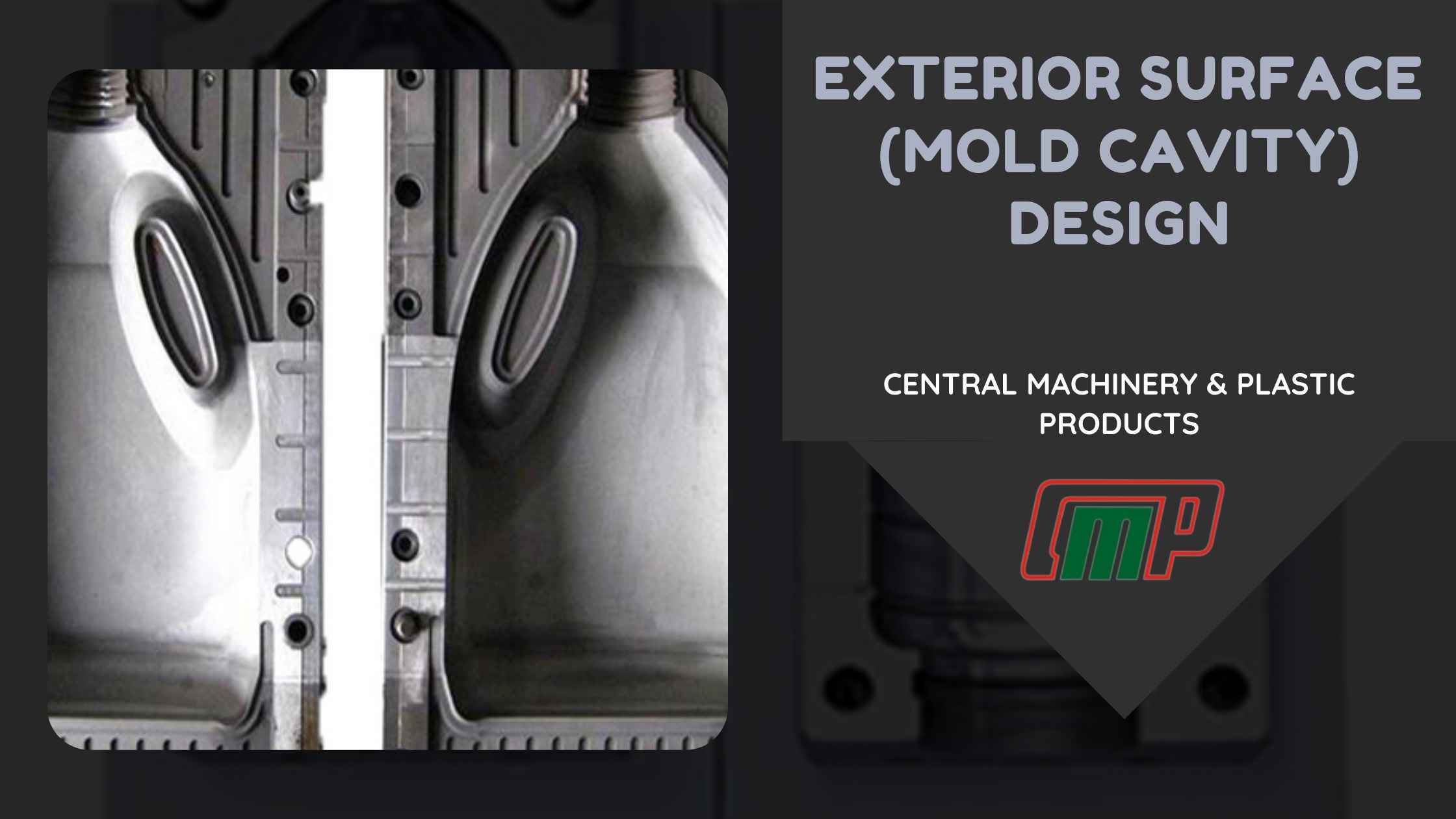
A bottle is a typical example of a blow moulded part formed using 2 cavity mould halves. A round bottle has a blow ratio that is comprised of a width=diameter and a depth=radius (2:1). The result is excellent material distribution in a round bottle. But, not all parts will be round. As designers start to push the limits of drawing down into cavities, how far should they go? The answer depends on the elongation elasticity of the material and how thin a wall you are willing to accept. But as a rule of thumb, the material won’t stretch much further down into a cavity (Depth=D) than the width of material available to fit into the cavity (Width=W). So, try not to design your cavity-cavity part to be deeper than the width.
Cavity – Core Blow Ratio = W>2D
Many industrial parts are formed using a combination of cavity and core mould elements where the core forms interior shapes. The core changes the blow ratio parameters.
The diameter of the cylindrical parison that forms a double wall part must allow enough material to enter the mould to adequately form each half of the part. Half of the cylindrical parison is used to form the exterior half (cavity) of the part and the other half of the cylindrical parison forms the interior half (core) of the part. Since there is no flow of material along the mould walls (only stretching), it follows that the depth of the cavity (D) should be no more than one-half the length or width of the cavity(W). A part design utilizing cavity depths that exceed this relationship will be subject to severe thinning or blow-out. So like the relationship between diameter and radius, cavity-core parts should have overall blow ratios of W>2D.
With multiple or divided cavities each cavity should meet this W>2D requirement.
The design of certain complex parts will require changes in the parting-line location to stay within this relationship. These steps in the parting line must include clearance for repeated opening and closing of the mould halves and be positioned so they do not shear the parison during mould-close. A parting line angle of 10° draft or greater is generally designed into mould parting line steps. When a 10° draft is not possible, options like angling the mould in the machine so that the parting lines form a positive draft relative to one another or moving mould sections can be used.
Sidewalls & Draft
The plastic parison sticks and begins to solidify as soon as it hits the mould. The material then stretches to fill the cavity as blowing progress. There is no flow of material along the mould walls. There are three aspects of thinning to consider.
- The thinning caused by stretching results in weakness. Any thin, weak location is susceptible to further thinning because it has become thin & weak. The thinning progresses rapidly in these locations.
- The apparent rigidity (or strength) of any area on the part varies proportionately with the square of the wall thickness.
- Variation in wall thickness can result in warpage.
The thinning along sidewalls and in corners is the reason that parts should have outside draft angles. The exterior draft is not critical to part removal from cavities since the plastic shrinks away from the outer mould walls as it cools. The draft is recommended when exterior walls are to be textured.
Plastic contouring of heavy parison sections to match these critical areas can improve the condition but not eliminate it. Because of this, cavity design must avoid features that contribute to thinning. Designs that utilize sharp 90° corners will result in parts with extremely thin, weak corners. There are a variety of corner configurations that improve or alleviate this problem. The most common approach is angling the sidewall and putting a radius or a chamfer-angle at the corner.
Part removal may be a problem with back-draft sections. Back-drafted areas can lock the part in the mould. If possible, apart from the backdraft on one side should have an equal positive draft on the opposite side. Thus, apart from a 15° backdraft on one side and a 15° positive draft on the other side can be removed like a part with no draft. Otherwise, moulds may need moving sections to remove the back drafted feature.
Shrinkage & Warpage
Shrinkage varies by material, the rate of temperature change and the thickness of the material. For PP and PE materials, the material thickness is the best predictor. Thin wall parts may shrink as little as 1% and thick parts over 10%. A .060” thick part will shrink approximately 1.65% as it cools and a .125” thick part will shrink about 1.85%. The shrinkage expectation must be taken into consideration when setting the mould size.
Designs that allow wall thinning variation to occur in the part may result in warped parts. The thin areas will shrink less before cooling than the thick areas. The variation in shrinkage rates and distances can cause the part to warp. Some wall thickness & shrinkage variation occurs in every moulded product because the cooling rate of the plastic will vary. The skin of the material against the mould metal will cool and take a set before the material does not touch the mould metal. The result is a tendency for outer walls to warp inward and is offset by the tendency of the inner wall to warp outward. The use of structural ribs, welds between walls, arcs or steps can create a structure that helps reduce warpage.
Cooling
To control dimensions, surface appearance and warpage, it is important to have as much control over the cooling of the part as possible. Flow rate is a major factor in heat removal and cycle time. By creating turbulent flow, heat extraction and cycle times can be improved. To control warpage in many designs, it is essential that mould cooling be targeted to provide extra heat extraction in the heavier wall portions of the part. The overall flow pattern also affects the part quality. The water warms as it flows through the mould.
The mould should contain several inlets and outlets in an oscillating cooling pattern.
A cold mould surface can also cause problems in reproducing surface details such as texture. Tooling engineers can target water lines near each critical section of the mould to provide the dimensional control and appearance you need.
Venting
When the mould closes the parison is captured at the pinch-off. A certain amount of air is trapped between the outside of the parison and the mould cavity. When air is blown to expand the parison, the trapped air becomes compressed by the expanding parison until an interior – exterior pressure equilibrium is reached. When this occurs, the parison will not completely touch the mould wall. The results are visible surface abnormalities, loss of texture & engraving detail, the appearance of creases and drag-lines, and longer cycles from poor mould cooling.
Venting can be easily located at the edge of an insert in the cavity. Slotted vent inserts or porous metals can be purchased and fit into nearly any location. Some venting methods will produce visible markings on the finished part. Texture, inserts and other techniques can be employed to mask the markings made at the vent location.