Blogs
DESIGN GUIDELINES FOR BLOW MOULDING MOULD
1) Blow Mold Guide
Guide pins and guide bushings from common standard parts suppliers are usually used as blow mold guides. The guide length should not exceed 1 * D. This is particularly important for mold movement machines to avoid damaging the parallel guidance of the clamping unit and the blow mold guide. The bore for the bushing must be drilled towards the rear of the mold or be cleared laterally to be able to easily remove pressed in material and ensure a clean closing of the blow mold.
2) Cutting Edges
The mold closes around the extruded the parison, thus squeezing and welding it. The cutting edge geometry must ensure that the flash can be easily separated from the article and a good weld seam quality is achieved.
In most cases, a compromise between weld seam quality and an easy flash separation is made. In case of doubt, however, the decision is always made in favor of the weld seam quality.
With a slow mold closing speed, a weld is obtained with a blunt cutting edge, but poor flash separation. A faster mold closing speed produces a poor weld seam, but better flash separation.
Weld seam quality depends, next to the designed weld seam geometry, the flash chambers, the machine setting, and other criteria, on the following factors:
* Material to be processed
* Parison wall thickness
* Melt temperature
* Support air adjustment
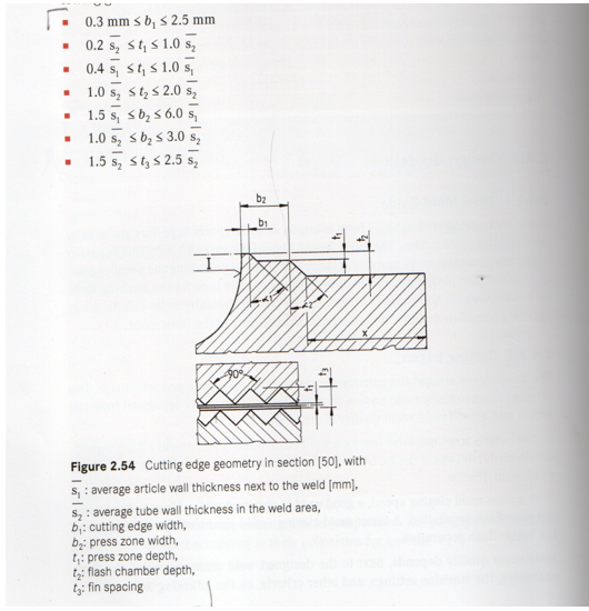
Figure 2.54 shows a sectional view of a conventional edge geometry. The flash area x is often ribbed for better cooling ( enlargement of the surface. ) The following guide values can be used for cutting edge design:
The design of the cutting edge has a significant influence on the clamping force required for flash pre-separation. In Section 2.3.7 , some raw material- dependent guide values for the specific closing force [ N per mm cutting edge length] are given. Coextrusion parts with a multilayer wall structure made of different materials and parts based on the barrier material ‘’Selar RB” (DuPont) are particularly critical for the weld seam. However, there are suitable weld seam geometries with sufficient strength properties for all applications (Figure 2.22).
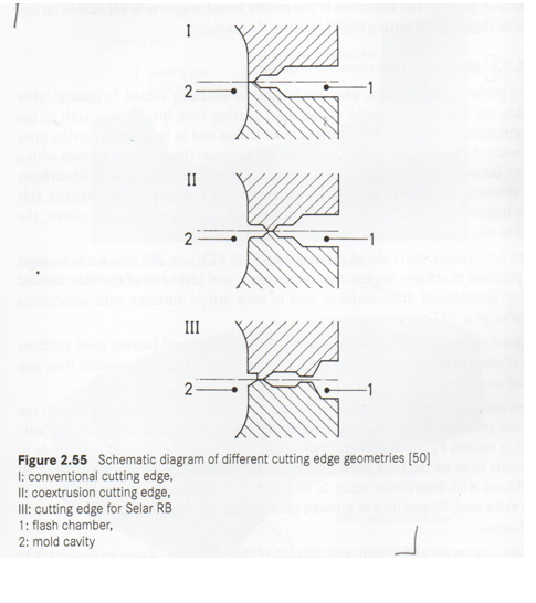
It is important for coextrusion welds that the multilayer composite is neatly layered and undisturbed up to the end of the weld [28].