Blogs
Blow Mold Cooling
The most important in the article production chain is the blow mold cooling. The cooling and blowing time determine the cycle time of the blow molding process and thus the production quantities. The cooling time accounts for about 70 to 80% of the total cycle time. The better the mold cooling, the colder the article can be demolded and less deformation due to post-shrinkage or warpage occurs. The cooling system must be designed to achieve the highest possible cooling water flow with a constant cooling cross-section.
Figure shows cooling system that are used in blow mold construction. Depending on mold material and article to be blown, different cooling system can be used on one blow mold. The use of cooling cartridges and 3D metal print parts is also possible, with the current use of 3D CAD programs. It is very easy to create the best possible cooling system for the respective requirements.
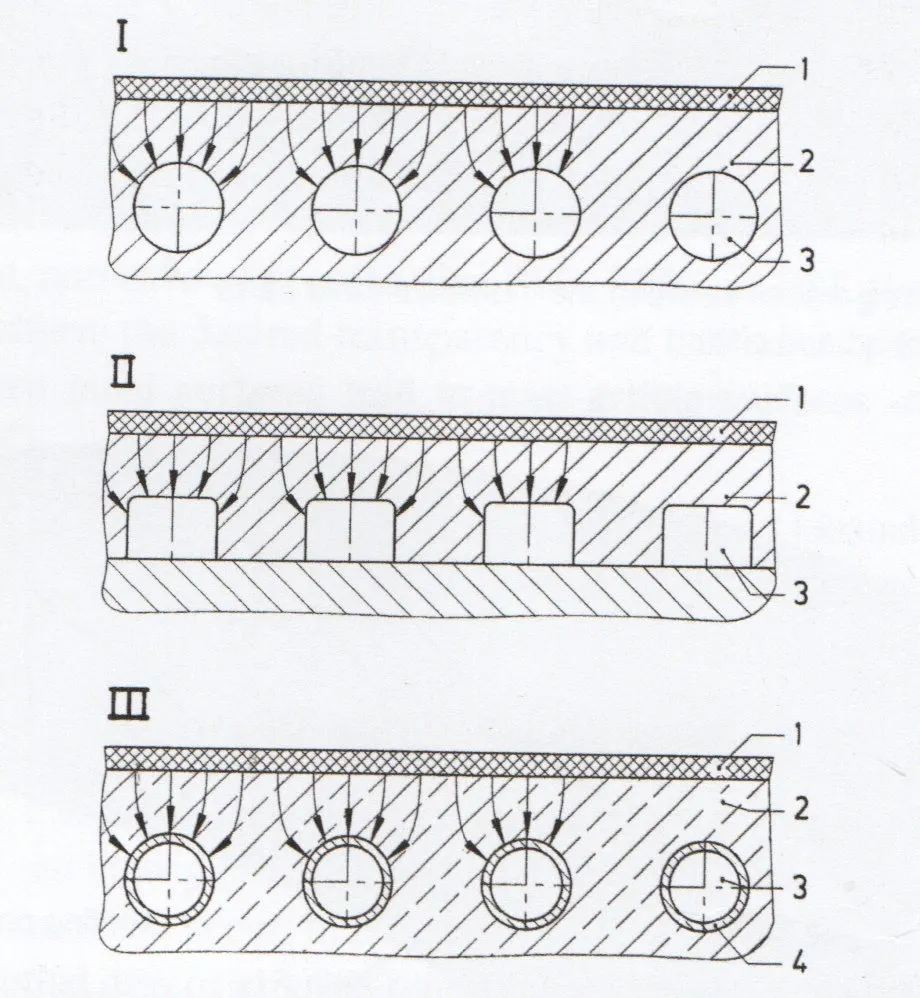
Schematic diagram of different blow mold cooling system [50] l: drilled cooling, ll: milled cooling, lll: cast-in tube cooling
1: blow molded part, 2: mold body , 3: cooling channels, 4: cooling pipes
(The arrows represent the heat flow.)
Drilled cooling
Drilled cooling is used for steel mold, block aluminum molds, and mold inserts.
For steel inserts and steel molds. The cooling channels should be as close as possible to the mold wall, with small hole spacing to achieve good cooling performance. Block aluminum offers greater cooling ranges than steel, as aluminum has approx. five times the thermal conductivity (Table 2.2).
Milled cooling
Milled cooling system (shell cooling system) are mostly used where intensive cooling cannot be achieved with a drilled cooling system, e.g. for shoulder sections of packaging parts, recessed bottom sections, neck inserts, or in preform molds for extrusion stretch blow molding.
In the case of milling or shell cooling, it must be considered that the coolant will flow against the mold wall to achieve optimum cooling behavior. Deflection plugs or baffles are used as additional barriers.

Cast-in Pipe cooling
Zinc casting molds are cooled by copper pipes. With the help of bends, the mold cooling can be adapted to the article shape and laid tightly to the article surface. Figure 2.59 shows a cooling cage with tow cooling circuits for a drum blow mold. The cooling pipe distance is 40 mm; the distance of the cooling pipes from the mold cavity is 10 mm. The zinc mold in combination with the copper pipe cooling features a very good thermal conductivity.
Cooling cage for drum blow mold made of copper pipe; body cooling wit tow cooling circuits per mold half; in the area of the engraving inserts the cooling is offset (Image: Kautex Maschinenbau)

A steel pipe cage is used for cast aluminum molds; copper pipe cooling is not an option due to the relatively high melting temperature of aluminum. The steel pipe cage is more expensive to manufacture than the copper cage and naturally has poorer heat transfer properties. Figure 2.60 shows a stainless steel tubular steel cage for a tank mold. There are areas foe an unscrewing device or mold inserts.
Stainless steel cooling pipe cage for PFT blow molding; slide areas and areas for boring inserts are optional [50]
The blow mold cooling system must be designed to dissipate the maximum possible amount of heat to achieve economical cycle times. However, the cycle time is limited by the thermal conductivity of the plastics.
In general, the cooling time shows a quadratic dependence on the article wall thickness. This results from the Fourier relationship (key figure for unsteady heat conduction processes; the same of number means the same degree of cooling of the article):
with tk cooling time, S article wall thickness, a thermal conductivity.
An important influencing parameter on the cycle time is the coolant temperature, which is influenced by the dew point in the mold area. If the dew point is undershot at any point in the mold cavity, condensation occurs, the mold ‘’sweats’’ , and the blow molded part shows corresponding marks. The dew point can be reduced if the mold area is sir-conditioned [30]
The flow cross-sections of cooling system are adapted to the article. It is important to achieve a turbulent flow with the lowest possible drop in pressure.
To further reduce the cycle times, the following options are available.
* Internal cooling of the blow molded part with cryogenic air (cycle time reductions up to 30%);
* Cooling with post-cooling mold (cooling time reductions up to 50%);
* Reduction of non-productive time through parameter optimization and increase of machine speeds (is largely exhausted on modern blow molding machines). A further reduction may create service life problem of the system.