Blogs
RADIAL WALL THICKNESS DISTRIBUTION IN BLOW MOULDING
In blow moulding, the wall thickness distribution of the finished article is essentially determined by the wall thickness distribution of the parison, its position in relation to the blow mould cavities, and the local stretching paths.
On the one hand, falling below a given wall thickness specification leads to defective articles. On the other hand, an oversupply of material in other areas causes unnecessary costs and also has a negative effect on the cooling time and thus on the cycle time.
To achieve the goal of efficient production with maximum output at minimum material and energy consumption, standard axial wall thickness control is not sufficient for articles with complex geometries.
The optimization of the radial (partial) wall thickness distribution of a blow moulded hollow part not only increases the economic efficiency of the production process, but also enables a sustainable blow moulding process with a significant reduction in CO2 emissions by reducing the amount of material used and the energy required per article produced (reduction of the required plasticizing and cooling capacity).
Special wall thickness control system for influencing the radial wall thickness distribution over the circumference of the parison are described in the following sections.
There are currently 2 major system being used in the process,
- SFDR – Statically Flexible Deformable Ring
- PWDS – Partial wall thickness distribution system
The details of both the system will be shared in the next blog.
Statically Flexible Deformable Ring (SFDR®)
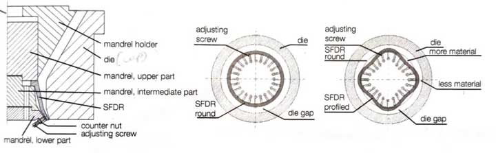
While the standard (axial) wall thickness control WDS = Wall-thickness Distribution System), as described in Section 2.3.5, is sufficient for simple rotationally symmetrical articles such as round bottles, articles with a rectangular cross-section (e.g. rectangular bottles or jerry cans) or with complex geometry are expected to have thin spots in the area of large stretch ratios, such as in the area of corners, shoulders, or edges. The thinnest point over the circumference determines the die gap to be set to meet the wall thickness specification and thus the material used for this cross-section. However, since the material supply is constant over the cross-section when using axial wall thickness control, thick spots appear on the article in the areas of low stretching. Here, in a first step, machining (profiling) of the die can help. This leads to an influence on the wall thickness distribution over the circumference of the parison, which is effective over the entire length of the parison. For each optimization step, the die must be removed again and again and the die ring or core pin must be machined until the optimum profile is achieved. When using the “statically flexible deformable ring” (SFDR®) as part of the mandrel, for a likewise defined radial influence on the parison wall thickness, the mandrel is profiled by deforming a flexible ring using adjusting screws. The advantage of the SFDR is that the profiling can be adapted t the requirements without dismantling the mandrel simply by adjusting the screws. This allows for quick optimization of the article without the risk of overshooting the mark. To optimize a product change with regard to set-up time and reproducibility, SFDR systems with exchangeable inserts are state-of-the-art nowadays. The exchangeable inserts can be changed within the few minutes and allow the SFDR profile to be adapted to the new product without having to remove the mandrel tool or adjust the adjusting screws.
Partial Wall Thickness Distribution System (PWDS®)
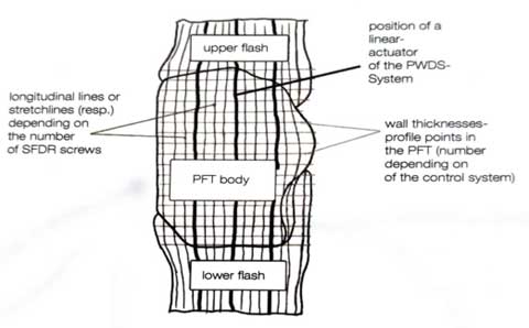
The radial die gap and thus the parison wall thickness over the circumference is the PWDS® system. Preferably in combination with the static profiling of an SFDR, the PWDS allows variable (dynamic) adjustment of the wall thickness distribution over the parison length. A “dynamically flexible deformable ring” (DFDR) is deformed by two servo-hydraulically or electrically driven actuators by pushing and/or pulling during parison ejection according to the specification of one or more profile curves. For each wall thickness point of the profile curve, the radial die gap is partially adjusted over the circumference. In combination with the standard wall thickness control, the PWDS system allows optimum adjustment of the parison wall thickness both over the circumference and in the axial direction.
Below figure shows a schematic illustration of the principle course of the profile points of the wall thickness control and the longitudinal or stretching lines corresponding to the adjusting screws of the SFDR in the case of a PFT.